Creating a Voracity Flow from the Palette (Part 1…
This is the first of two articles showing how to create and use job flows in the IRI Workbench GUI for Voracity. It follows two other series on creating flows automatically using new job wizards.1 We will create the same flow built in the second series, but this time directly through the flow diagram editor.
With this “design from scratch” method, start with a basic flow building block, or “flowlet”, then add to it by dragging components from the Palette into the flowlet.
Remember that flows contain Extract-Transform-Load (ETL) and other data processing steps that are illustrated in flow and transform mapping diagrams in Workbench. They are saved in .flow files for execution from IRI workbench, or serialized as .sh or .bat files for execution from inside or outside the Workbench.
The flow we are making here matches data in an Oracle table called PATIENT_RECORD with billing information from the PATIENTBILLING table, then it sends the results to collections. Some of the data in the PATIENT_RECORD table is sensitive. After extracting the data from the table, this phase of the job will mask some of the columns and eliminate others.
Begin by creating a project in IRI Workbench called ScratchFlow to hold all the files associated with this Flow. Make sure this project is highlighted in the project explorer before continuing.
Create the Flowlet
Click File on the menu bar > New > Flow. Type in Scratch.flow for the File name, then click Finish.
Scratch.flow is now in your project and is open in the editor. Click on Batch: unnamed in the editor. Look at the Properties view at the bottom of the screen. If the Properties view is not open, follow these steps to open it: click Window on the menu bar > Show View > Properties. Currently, Batch has Name: unnamed. Change unnamed to Scratch, Click in the editor, then click Save All on the navigation bar. In both the editor and the project, you now have Batch: Scratch under Scratch.flow.
In the project, right-click on Batch: Scratch > New Representation > new Flow Diagram. Type in Scratch Flow Diagram for the Representation name and click OK. Click in the gray flowlet, then select Base in the Properties view, and change Name to Scratch. Click in the flowlet again.
If New Representation is not a choice, follow these steps:
Right-click on the Project name in the Project Explorer and click Viewpoint Selection. Put a check in the Flow box and click OK. Then go back and follow the previous steps.
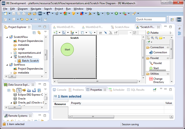
A flowlet is created and displayed in the editor. It consists of a gray flowlet block that contains a green Start block as shown below.
We will create two data transformation jobs in the flowlet: PatientInfoProtect.scl and Collections.scl. The second will be created in the next article. They will each be represented in the flow by a Transform Mapping Block. You can visualize the contents of those blocks in transform mapping diagrams and in SortCL scripts once those scripts have been created.
Create the First Transform
Drag a Transform Mapping Block from the palette on the right into the flowlet. The Transform Mapping Block diagram is the visual representation of a SortCL script where you can follow the source-to-target field mappings in addition to any transforms that are performed.
Double-click in the Transform Mapping Block to see a detailed view of the block. For Representation name, type PatientInfoProtect Mapping Diagram, then click OK. There are blocks in this diagram, for Input Data, Action, and Output Data.
From the Palette on the right, drag an Input ODBC icon and drop it into the Input Data block. This will bring up the Database Information window. Select the Data source name(DSN) from the drop-down. The Table selection window will then populate with the tables available for that DSN. Click the checkbox for NIGHTLY.PATIENT_RECORD, then click Finish.
The Input Data block now has a white source block with a table named PATIENT_RECORD, which contains a blue block for fields or columns. It also has a yellow Section Options block containing items that apply to the table or file as a whole.
Click in the white source block. Then click Arrange Selection from the drop-down menu in the upper left corner of the editor.
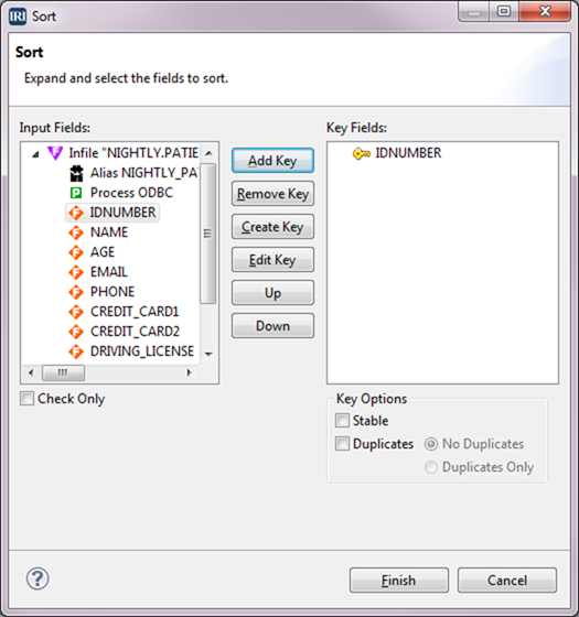
The next Transform Mapping Block of this flow will perform a join on IDNUMBER. Therefore, we can sort here using that field as the key. From the Transform Action section of the Palette, drag the Sort icon into the Action block. This brings up the Sort window.
Select IDNUMBER from the Input Fields box and select Add Key. IDNUMBER is now displayed in the Key Fields box. You can repeat the process for as many keys as are necessary for the sort. In this instance, we only need one key. Click Finish.
The Action block is populated with a white Sort block that contains a gray block with the fields from the input, and an orange Action Key block containing the key that was just defined.
Define the Target
Drag the File icon from the Output section of the Palette into the Output Data block. The Output Selection Type dialog will open. Because we need to define the output format for our target, select Editor to open the Target Field Layout editor.
The top half of the editor has source definitions, and the bottom half has target definitions. Initially, the target has the name Out_File and all the input fields have been copied to the target. If you want, you can click the trash icon to delete all the fields in the target, and then drag the desired fields from source to target.
Since we want most of the fields, we will, instead, remove the fields that we don’t want. We will remove AGE, EMAIL, DRIVING_LICENSE, and SSN. For each one, right-click on the field and select Remove. With those fields gone, the field positions need to be recalculated by clicking the 1-2-3 icon.
Mask the Credit Card Numbers
There are two fields for holding credit card numbers. These need to be masked so that only the last 4 digits of the numbers can be viewed. Right-click on the field CREDIT_CARD1 > Apply Rule > Create Rule.
Click Masking Function under Protection Rules and verify that the Library location has our project name. Type CreditCardMask for the Rule name, and click Next.
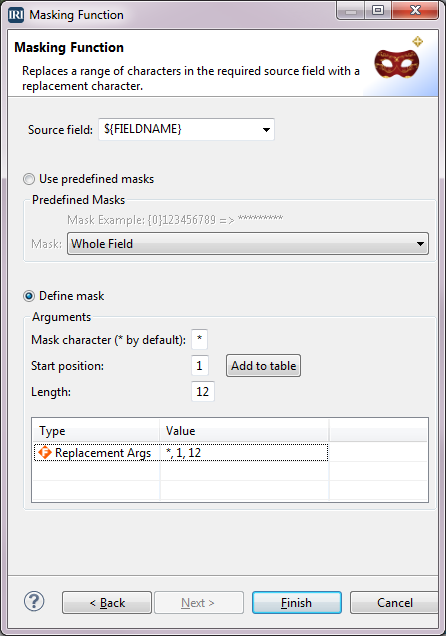
In the Masking Function window, select Define mask. Type * for Mask character, 1 for Start position, 12 for Length, and then click Add to table. The definition is added to the table at the bottom. Click Finish.
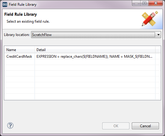
We have returned to the Target Field Layout editor and now want to mask the other credit card field. We already created the masking rule for credit cards, so we want to use that rule. Right-click on the field CREDIT_CARD2 > Apply Rule > Browse Rule. When the Field Rule Library window opens, select the rule named CreditCardMask, and then click OK.
The two credit card fields now have the Field designation of Function. Also, the field names have been changed to MASK_CREDIT_CARD1 and MASK_CREDIT_CARD2 because these are now derived fields. Click OK.
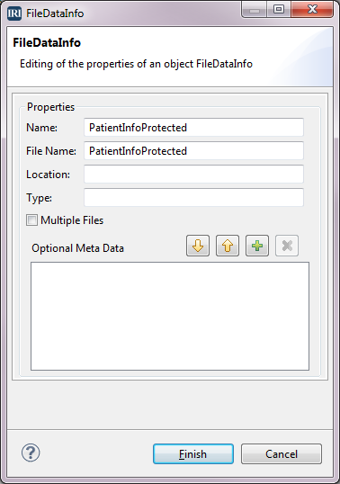
We are now back in the PatientInforProtect Transform Mapping Diagram. Click in the white Out_File block. In the Properties view, select Base, then change Name to PatientInfoProtected. Now, select the . . . button next to the Data Info field to go to the FileDataInfo dialog. Change the Name to PatientInfoProtected and File Name to Out_PatientInfoProtected, and then click Finish.
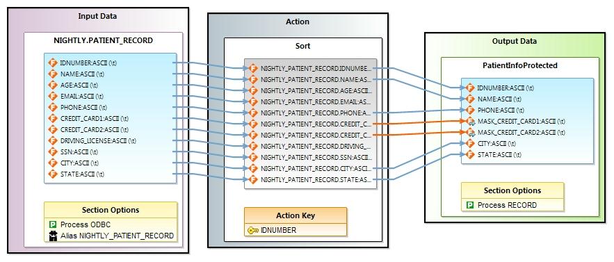
The input file with fields are displayed in the Input Data block. You can follow the fields through the Action block where, in this case, the sort key is defined. Then, follow the connection arrows that map the fields into the blue field block of the Output Data block.
Notice that not all fields were mapped into the output, and that the two fields where masking was applied have orange connecting arrows, instead of blue. This is because a masking function was applied to the values in the original fields before being accepted to the output.
For more details on these major Voracity task blocks, see Creating a Voracity Flow Using Existing IRI Scripts (Part 1).
Now click in the area outside the blocks. Select the Base tab in the Properties view. Change Name and IRI Job to PatientInfoProtect.scl. The first field names the Transform Mapping Block represented in the above diagram, and the second field names the SortCL Job script that will be created from that diagram.
Define the Metadata for Data File PatientInfoProtected
Because the output file PatientInfoProtected will be used as an input file for the second Transform Mapping Block, we need to create a DDF (metadata) file specifying the layout for that file. That layout is currently available in the blue field block for the Output Data file represented in the above diagram. Right-click in the blue block for the fields in the Output Data block > IRI Diagram Actions > Create DDF. Keep the File name PatientInfoProtected.ddf in the DDF Options dialog and click Finish. The DDF file is now in the metadata directory of our project and can be referenced when the second Transform Mapping Block is created in the next article.
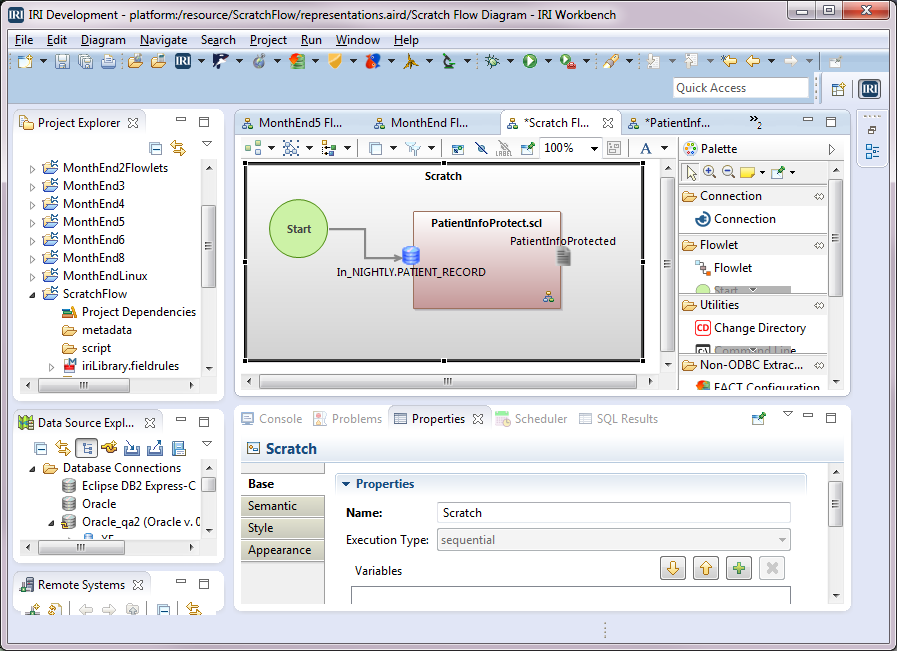
Return to the Scratch Flow Diagram in the editor. Connect the Start block to the input table for the transform mapping block named PatientInfoProtect.scl by clicking the Connection icon in the Palette. Then click the Start block, followed by the icon for the input table PATIENT_RECORD. In the diagram below, you can see the flow named Scratch that was created.
Serialize the Job for Execution
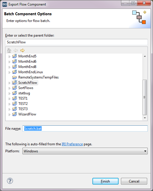
To create the job script PatientInfoProtect.scl and the batch file for this flow, right-click in the editor > IRI Diagram Actions > Export Flow Component. Select Windows from the Platform drop-down and verify that Scratch.bat is in the File name field. This is the name of the file that will execute the flow. Click Finish. The CoSort/SortCL Job script and the batch file are created and placed in the project.
Note that flow and batch files can contain multiple components in addition to transform blocks (SortCL scripts), including blocks for IRI FACT (fast extract) or bulk DB load tasks, SQL and command line programs, FTP and decision blocks, etc.
Review the Transform Script
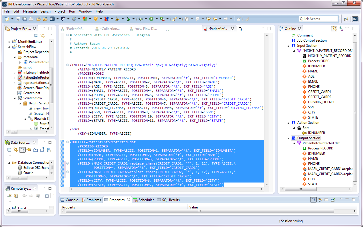
After the job script PatientInfoProtect.scl has been generated, it can be displayed in the editor by double-clicking on that .scl file in the Project Explorer. Red items in the editor indicate syntax keywords, and blue items indicate strings.
In the Model outline to the right of the editor, you can click an item and see it highlighted in the editor. For example, if I click Output Section in the outline, the output section of the (SortCL job) script is highlighted:
You can also right-click on items in the outline to edit them, or in the script editor. This will open IRI menus with editing options. Any edits made to the script are not automatically reflected in the flow (you must save the script and drag its file back into the flow), but it’s another way to make changes.
Following are the batch script and the job script it can execute. This is done from within IRI Workbench directly, through its task scheduler, any third-party job scheduler, or from the command line:
The“Scratch.bat” file contains:
@echo off
sortcl /SPECIFICATION=PatientInfoProtect.scl
The PatientInfoProtect.scl job we created contains:
/INFILE="NIGHTLY.PATIENT_RECORD;DSN=Oracle_qa2;UID=nightly;PWD=N321ghtly;"
     /ALIAS=NIGHTLY_PATIENT_RECORD
     /PROCESS=ODBC
     /FIELD=(IDNUMBER, TYPE=ASCII, POSITION=1, SEPARATOR="\t", EXT_FIELD="IDNUMBER")
     /FIELD=(NAME, TYPE=ASCII, POSITION=2, SEPARATOR="\t", EXT_FIELD="NAME")
     /FIELD=(AGE, TYPE=ASCII, POSITION=3, SEPARATOR="\t", EXT_FIELD="AGE")
     /FIELD=(EMAIL, TYPE=ASCII, POSITION=4, SEPARATOR="\t", EXT_FIELD="EMAIL")
     /FIELD=(PHONE, TYPE=ASCII, POSITION=5, SEPARATOR="\t", EXT_FIELD="PHONE")
     /FIELD=(CREDIT_CARD1, TYPE=ASCII, POSITION=6, SEPARATOR="\t",       EXT_FIELD="CREDIT_CARD1")
     /FIELD=(CREDIT_CARD2, TYPE=ASCII, POSITION=7, SEPARATOR="\t",    EXT_FIELD="CREDIT_CARD2")
     /FIELD=(DRIVING_LICENSE, TYPE=ASCII, POSITION=8, SEPARATOR="\t", EXT_FIELD="DRIVING_LICENSE")
     /FIELD=(SSN, TYPE=ASCII, POSITION=9, SEPARATOR="\t", EXT_FIELD="SSN")
     /FIELD=(CITY, TYPE=ASCII, POSITION=10, SEPARATOR="\t", EXT_FIELD="CITY")
     /FIELD=(STATE, TYPE=ASCII, POSITION=11, SEPARATOR="\t", EXT_FIELD="STATE")

/SORT
/KEY=(IDNUMBER, TYPE=ASCII)

/OUTFILE=PatientInfoProtected
     /PROCESS=RECORD
     /FIELD=(IDNUMBER, TYPE=ASCII, POSITION=1, SEPARATOR="\t", EXT_FIELD="IDNUMBER")
     /FIELD=(NAME, TYPE=ASCII, POSITION=2, SEPARATOR="\t", EXT_FIELD="NAME")
     /FIELD=(PHONE, TYPE=ASCII, POSITION=3, SEPARATOR="\t", EXT_FIELD="PHONE")
     /FIELD=(MASK_CREDIT_CARD1=replace_chars(CREDIT_CARD1, "*", 1, 12), TYPE=ASCII, POSITION=4, SEPARATOR="\t", EXT_FIELD="CREDIT_CARD1")
     /FIELD=(MASK_CREDIT_CARD2=replace_chars(CREDIT_CARD2, "*", 1, 12), TYPE=ASCII, POSITION=5, SEPARATOR="\t", EXT_FIELD="CREDIT_CARD2")
     /FIELD=(CITY, TYPE=ASCII, POSITION=6, SEPARATOR="\t", EXT_FIELD="CITY")
     /FIELD=(STATE, TYPE=ASCII, POSITION=7, SEPARATOR="\t", EXT_FIELD="STATE")
In the next article, we will add to the flow by defining a second Transform Mapping Block. The output from the script, represented here by the Transform Mapping Block PatientInfoProtect.scl, will become one of the inputs for the new Transform Mapping Block.
- These articles show different ways to create and modify ETL jobs in Voracity’s Eclipse GUI. The first series covered flow construction from existing transform jobs already expressed in CoSort SortCL programs (scripts). The second and third series are for those new to IRI technology who prefer to build and modify the underlying job scripts graphically.
