Creating a Voracity Flow from a Wizard (Part 1…
Abstract: The IRI Voracity data management platform provides data integration tools, including data pipeline automation for high-performance ETL (Extract-Transform-Load) operations. This article is the first in another series on how to create and use high-performance ETL workflows in the IRI Workbench GUI for Voracity. It follows the first series of articles on creating flows from existing CoSort/SortCL (ETL) job scripts.
In this article, we create an Voracity ETL workflow using one of the built-in job creation wizards in the toolbar menu of IRI Workbench. Many ETL tools do not provide wizard-driven job design; for Voracity, this is only one of several ways to build out your jobs.
Remember that flows contain and other data processing steps, which are illustrated in flow and transform mapping diagrams in IRI Workbench. They are saved in .flow files for execution from IRI Workbench or serialized as .sh or .bat files for execution from inside or outside IRI Workbench. Wizards can be used to create either job scripts or flows that include them.
This flow matches data in an Oracle table called PATIENT_RECORD with billing information from the PATIENTBILLING table, then sends it to collections. Some of the data in the PATIENT_RECORD table is sensitive. After extracting the data from the table, this phase of the job will mask some of the columns and eliminate others.
We will begin by creating a project in IRI Workbench called WizardFlow to hold all the files associated with this Flow.
Create the Flow
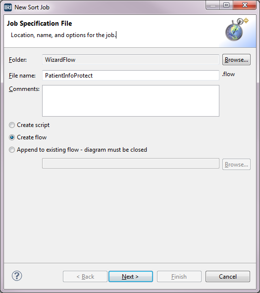
In this case, running the job wizard to completion will build a complete ETL flow, which can be modified later. To launch the wizard and begin creating the Flow, click the stopwatch icon in the toolbar to reveal the CoSort job menu. Select New Sort Job and type PatientInfoProtect for the File name. Select the Create flow radio button and click Next.
Define the Source
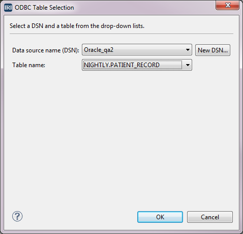
Our source is the table PATIENT_RECORD. To create the source definition, select Add Data Source in the Data Source dialog. Because the source is a table, select the ODBC radio button and click Browse. In the ODBC Table Selection dialog, select the Data source name and select the Table name PATIENT_RECORD from the drop-downs, then click OK.
Click OK again to return to the Data Sources dialog. We now need to create the field or column definitions. Select Discover Metadata to bring up the Setup Options dialog. Type PatientRecord for the File Name field and click Next.
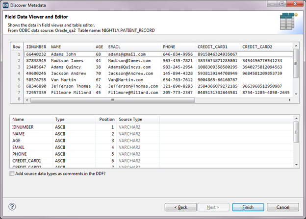
In the Data Source Identification dialog, verify that the information about your table is correct, then click Next to open the Field Data Viewer and Editor. The upper half contains a sample of the data from the table, along with the column names. The bottom half contains the column names, CoSort-equivalent data types, position, and data types in the source table.
Click Finish, then click Yes to copy the fields into the Data Sources tree. This saves the field definitions to a reusable data definition file (DDF) so it can be referenced in this or another job. Click Next to open the Sort dialog where we will define a key.
Define the Sort Key(s)
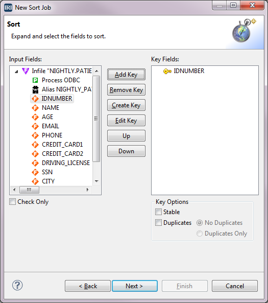
Because the next phase of this flow will join on the IDNUMBER field, we can sort on it by defining that field as the key.
Select IDNUMBER from the Input Fields box and select Add Key. IDNUMBER is now displayed in the Key Fields box. You can repeat the process for as many keys as necessary for the sort. In this instance, we only need one key. Click Next to go to the Data Targets dialog.
Define the Target
Select Add Data Target in the Data Target dialog. Select the File radio button, then type PatientInfoProtected.dat in the File field, and click OK.
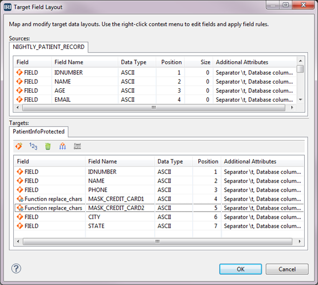
In the Data Targets dialog, select Target Field Layout. The top half of the dialog has source definitions and the bottom half has target definitions. Initially, all of the input fields have been copied to the targets. If you want, you can click the trash can icon and delete all the fields in the target PatientInfoProtected.dat, and then drag the desired fields from the source to the target.
Since we want most of the fields, we will, instead, remove the fields that we don’t want. We want to remove AGE, EMAIL, DRIVING_LICENSE, and SSN. For each one, right-click on the field and select Remove. With those fields gone, the field positions need to be recalculated by clicking the 1-2-3 icon.
Apply Protection
There are fields for two credit card numbers. These need to be masked so that only the last 4 digits of the numbers are displayed. Right-click on the field CREDIT_CARD1 > Apply Rule > Create Rule.
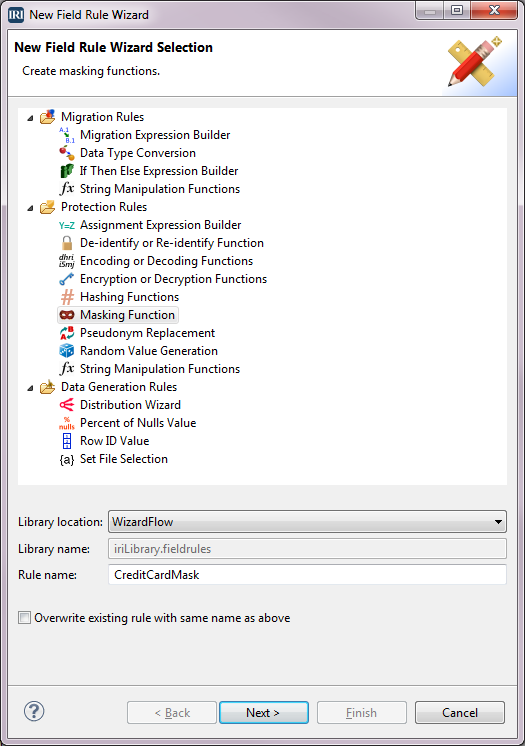
Click Masking Function under Protection Rules and verify that the Library location has our project name. Type CreditCardMask for the Rule name, and click Next.
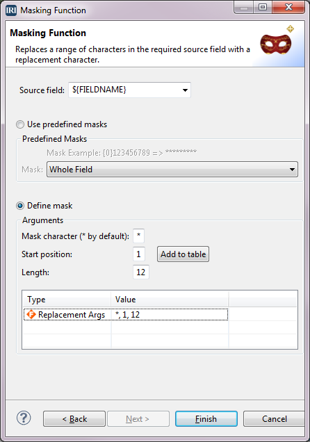
In the Masking Function dialog, select the Define mask radio button. Type * for Mask character, 1 for Start position, 12 for Length, then click Add to table. The definition is added to the table at the bottom. Click Finish.
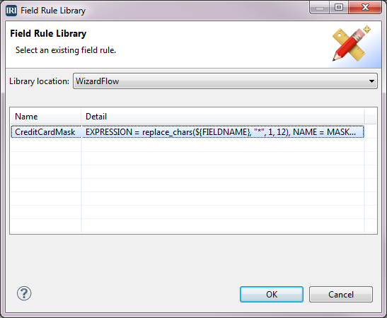
We have returned to the Target Field Layout dialog and now want to mask the other credit card field. We already created the masking rule for credit cards, so we want to use that rule. Right-click on the field CREDIT_CARD2 > Apply Rule > Browse Rule. When the Field Rule Library dialog displays, select the rule named CreditCardMask and click OK.
The two credit card fields now have the Field designation of Function, and the field names have been changed to MASK_CREDIT_CARD1 and MASK_CREDIT_CARD2 because these are now derived fields.
Click OK to return to the Data Targets dialog where the tree outline is displayed in the box on the left. Click Finish.
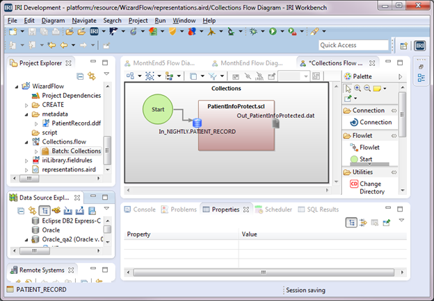
PatientInfoProtect.flow is now part of the project and displays in the editor. In the project, rename the flow to Collections.flow and then expand the flow. Right-click Batch: PatientInfoProtect.scl > New Representation > new flow diagram. For Representation name, type Collections Flow Diagram in the New Representation dialog, and click OK.
A flow is created and displayed in the editor. It consists of a gray flowlet block that contains a green Start block and a brown Transform Mapping Block named PatientInfoProtect.scl.
The Start block has an arrow connected to the icon for input table NIGHTLY.PATIENT_RECORD in the Transform Mapping Block. There is also an output file icon named PatientInfoProtected.dat.
Let’s change the name of the batch and the name of the flowlet from PatientInfoProtect.scl to Collections. Click in the white space around the flowlet. Then in the Properties view at the bottom of the screen, select Base, and type Collections in the Name field. Now click in the flowlet and do the same. The names are changed in the editor and in the Project Explorer.
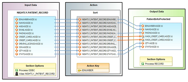
Double-click in the Transform Mapping Block and name the diagram PatientInfoProtect Transform Mapping Diagram. Click OK. This displays a detailed diagram of the job PatientInfoProtect.scl that we created using the New Sort Job option from the CoSort Menu.
The input file with fields is displayed in the Input Data block. You can follow the fields through the Action block where, in this case, the sort key is defined. Then follow the fields into the file block in the Output Data block. Notice that not all the fields were mapped into the output, and that the two fields where masking was applied have orange instead of blue connecting arrows. This is because a masking function is applied to the values in the original fields before being accepted to the output. For a more detailed explanation of these blocks, see Creating Voracity Flows Using Existing IRI Scripts (Part 1).
Now, go back to the Collections Flow Diagram in the editor. To create the job script PatientInfoProtect.scl and the batch file for this flow, right-click in the editor > IRI Diagram Actions > Export Flow Component. Select Windows from the Platform drop-down and verify that Collections.bat is in the File name field. This is the name of the file that will execute the flow. Click Finish. The CoSort/SortCL Job script and batch file are created and placed in the project.
Following are the batch script and the job script it can execute. This is done from within IRI Workbench directly, through its task scheduler, any third-party job scheduler, or from the command line:
Collections.bat
@echo off
 sortcl /SPECIFICATION=PatientInfoProtect.scl
PatientInfoProtect.scl
/INFILE="NIGHTLY.PATIENT_RECORD;DSN=Oracle_qa2;UID=nightly;PWD=N321ghtly;"
     /ALIAS=NIGHTLY_PATIENT_RECORD
     /PROCESS=ODBC
     /FIELD=(IDNUMBER, TYPE=ASCII, POSITION=1, SEPARATOR="\t", EXT_FIELD="IDNUMBER")
     /FIELD=(NAME, TYPE=ASCII, POSITION=2, SEPARATOR="\t", EXT_FIELD="NAME")
     /FIELD=(AGE, TYPE=ASCII, POSITION=3, SEPARATOR="\t", EXT_FIELD="AGE")
     /FIELD=(EMAIL, TYPE=ASCII, POSITION=4, SEPARATOR="\t", EXT_FIELD="EMAIL")
     /FIELD=(PHONE, TYPE=ASCII, POSITION=5, SEPARATOR="\t", EXT_FIELD="PHONE")
     /FIELD=(CREDIT_CARD1, TYPE=ASCII, POSITION=6, SEPARATOR="\t", EXT_FIELD="CREDIT_CARD1")
     /FIELD=(CREDIT_CARD2, TYPE=ASCII, POSITION=7, SEPARATOR="\t", EXT_FIELD="CREDIT_CARD2")
     /FIELD=(DRIVING_LICENSE, TYPE=ASCII, POSITION=8, SEPARATOR="\t", EXT_FIELD="DRIVING_LICENSE")
     /FIELD=(SSN, TYPE=ASCII, POSITION=9, SEPARATOR="\t", EXT_FIELD="SSN")
     /FIELD=(CITY, TYPE=ASCII, POSITION=10, SEPARATOR="\t", EXT_FIELD="CITY")
     /FIELD=(STATE, TYPE=ASCII, POSITION=11, SEPARATOR="\t", EXT_FIELD="STATE")

/SORT
     /KEY=(IDNUMBER, TYPE=ASCII)

/OUTFILE=PatientInfoProtected
     /PROCESS=RECORD
     /FIELD=(IDNUMBER, TYPE=ASCII, POSITION=1, SEPARATOR="\t", EXT_FIELD="IDNUMBER")
     /FIELD=(NAME, TYPE=ASCII, POSITION=2, SEPARATOR="\t", EXT_FIELD="NAME")
     /FIELD=(PHONE, TYPE=ASCII, POSITION=3, SEPARATOR="\t", EXT_FIELD="PHONE")
     /FIELD=(MASK_CREDIT_CARD1=replace_chars(CREDIT_CARD1, "*", 1, 12), TYPE=ASCII, POSITION=4, SEPARATOR="\t", EXT_FIELD="CREDIT_CARD1")
     /FIELD=(MASK_CREDIT_CARD2=replace_chars(CREDIT_CARD2, "*", 1, 12), TYPE=ASCII, POSITION=5, SEPARATOR="\t", EXT_FIELD="CREDIT_CARD2")
     /FIELD=(CITY, TYPE=ASCII, POSITION=6, SEPARATOR="\t", EXT_FIELD="CITY")
     /FIELD=(STATE, TYPE=ASCII, POSITION=7, SEPARATOR="\t", EXT_FIELD="STATE")
In the next article, we will use another CoSort job wizard in IRI Workbench to create a Transform Mapping Block that will be added to the flowlet created in this article. The output from the script, represented here by the Transform Mapping Block, will become one of the inputs for a new Transform Mapping Block.
